Specialized articles
Monitoring of reciprocating compressors

Preditec/IRM offers you the right technology for the protection, monitoring, [...]
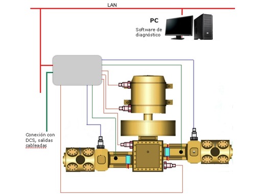
Preditec/IRM offers you the right technology for the protection, monitoring, and diagnostics of your reciprocating compressors.
Reciprocating compressors are critical machines in certain production processes. Therefore, a predictive maintenance strategy is essential to prevent:
- Unexpected breakdowns that halt the production process.
- Catastrophic failures that destroy the compressor.
- Decline in performance.
Reciprocating machines are difficult to diagnose using vibration analysis. The FFT analysis technique, which has been so successful with rotating machinery, does not provide useful information for diagnosing reciprocating machinery. However, there are other techniques—also based on vibration measurement and analysis—that have proven effective, such as waveform analysis. Vibration is typically measured in these machines as a general monitoring parameter as well as a diagnostic tool. The following diagram shows the main parameters for basic monitoring of reciprocating compressors:
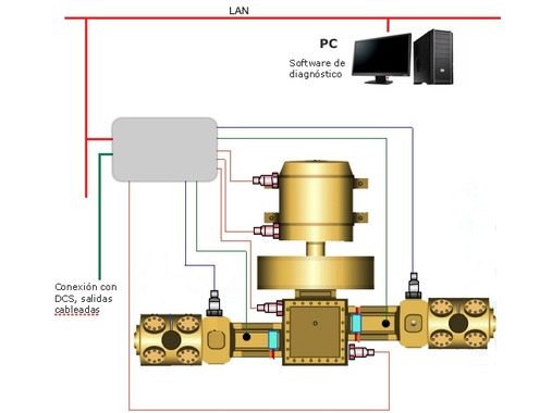
Vibration transmitters
Due to its operating principle, a reciprocating machine causes strong vibrations by alternately moving a significant mass. Reciprocating compressor designs aim to counteract these forces to minimize vibration, but when an imbalance occurs, the amplitude of this vibration increases. To detect these changes in vibration, vibration transducers are mounted on the base frame. These transducers send the overall vibration value in mm/s rms from various points on the compressor to the distributed control system (DCS). This parameter will alert operators to structural problems or significant misalignments that cause the compressor to vibrate at higher-than-normal levels. The vibration velocity is highly sensitive to changes in the system’s stiffness or to changes in the exciting forces.
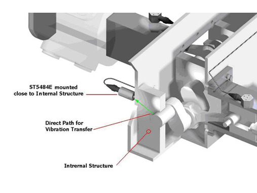
Vibration transducers are mounted on the compressor base in a horizontal orientation, aligned with the direction of piston travel.
Impact Transmitters
Looseness issues are best identified by analyzing the measured acceleration waveform. This analysis can be performed manually, but if you want to automate it in a simple way, you can use an impact transmitter, which is specifically designed for this task. Impact transducers measure high-frequency vibration (acceleration) and feature an impact counter. Their integrated electronics convert the measured vibration waveform into a scalar value indicating the number of times a set threshold has been exceeded within a specified time interval. For each compressor, a vibration level and a typical number of times the vibration wave exceeds the preset limit must be defined. This value is transmitted to the DCS for monitoring.
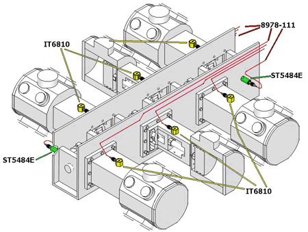
The impact transmitter is placed near the crosshead and alerts operators to mechanical problems such as play, friction, or poor lubrication.
Although this is a relatively new technique, the installation of these impact transmitters has become widespread.
Rod drop
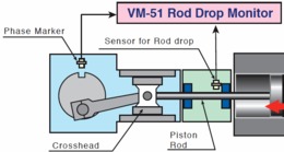 To monitor rod drop, a proximity sensor is installed to continuously measure the distance from a fixed point to the compressor rod. This captures a waveform of the connecting rod’s往复 motion. Comparing the recorded waveforms over time will alert operators to piston ring wear and other potential mechanical problems. Some rod drop monitoring systems are simplified by converting the proximity sensor’s measurement into a scalar value. Depending on how this conversion is performed, the monitoring value is more or less reliable.
To ensure the reliability of the monitored parameter, a single-point measurement must be taken each cycle outside the areas where the forces on the piston reverse; therefore, it is recommended that the measurement be synchronized with a tachometer.
Dynamic Pressure Analysis
But perhaps the technique that provides the most information for diagnosing reciprocating compressors is the analysis of the dynamic pressure in each cylinder. The representation of pressure over time for each cycle—or the actual P-V diagram—provides valuable information for compressor analysis, whether based on spot measurements taken with portable equipment or on continuous monitoring.
Ultrasound Analysis
Monitoring the condition of the valves in reciprocating compressors is essential due to the high failure rate of compressors caused by valve problems. The technique that best indicates valve problems is ultrasonic measurement of the cylinder head. The representation of the ultrasonic wave throughout each cycle (360° of crankshaft rotation) provides the information needed to locate faults, primarily in valves, but ultrasonic analysis also alerts us to other mechanical failures, such as clearance in the crosshead, piston ring wear, lubrication failures, etc.